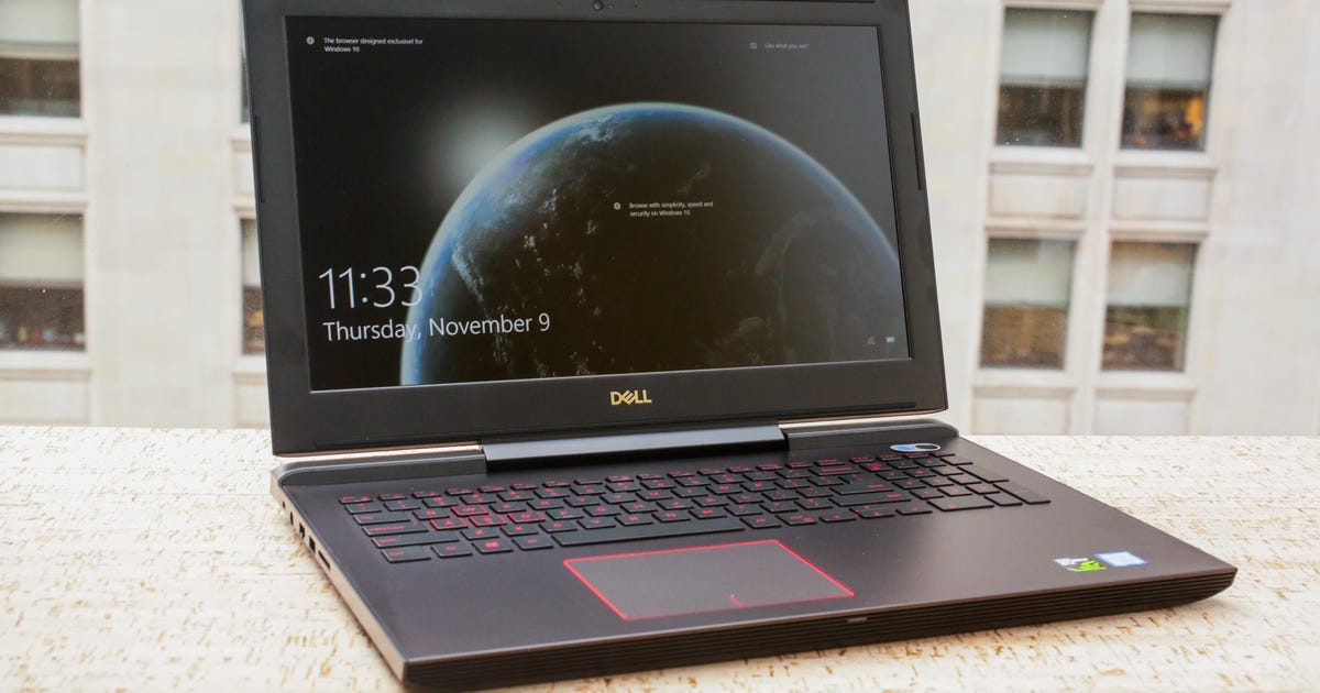
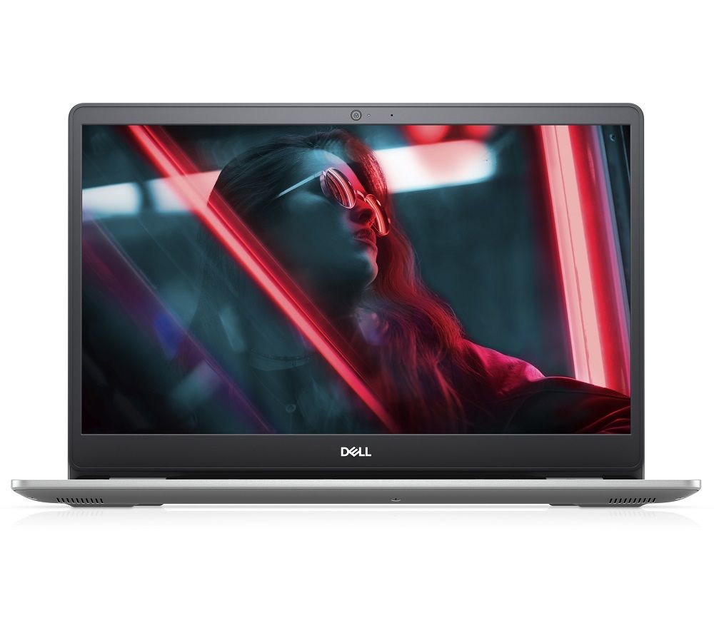
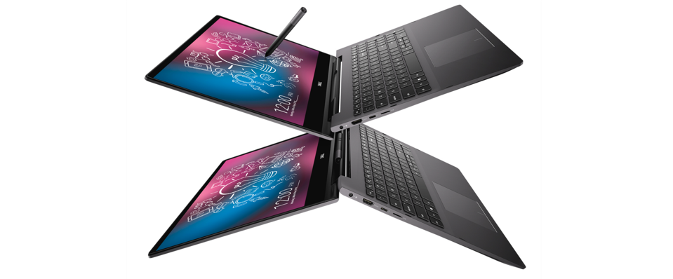
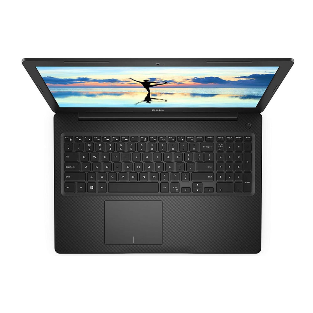
Dell inspiron 15 - Dell Inspiron 15 7000 vs. Dell XPS 15
DELL INSPIRON 15 OWNER'S MANUAL Pdf Download
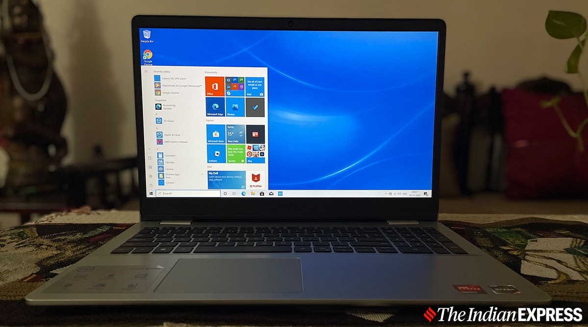
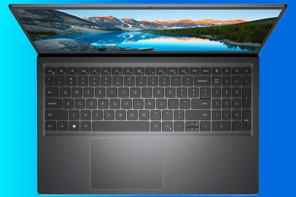
NOTE: Keyboard-backlight cable is present only on a backlit-keyboard. CAUTION: Hard drives are fragile. Peel off the antenna cable from the system board. 10 Recommended Tools After Working Inside Your Computer. Align the camera to the alignment posts on the display back-cover. Procedure Align the display bezel with the display back-cover and gently snap the display bezel into place. Procedure Place the hard drive in the hard drive bracket and align the screw holes on the hard-drive bracket with the screw holes on the hard drive. 14 Procedure Removing the Battery. Pry the power-adapter port out of the slot on the palm rest. After Working Inside Your Computer. Dell Inspiron 15-3567 is a Windows 10 Home laptop with a 15. Procedure Using your fingertips, gently pry up the inner edges of the display bezel. screws 9 base frame Using your fingertips, starting from the rear, pry the base frame off the palm-rest assembly. 68 Procedure Replacing the Palm Rest. For more safety best practices, see the Regulatory Compliance home page at dell. As of 28th May 2021, Dell Inspiron 15-3567 price in India starts at Rs. 87 Getting Help and Contacting Dell. Procedure Slide the power-adapter port into the slot in the palm-rest assembly. 53 Procedure Replacing the Status-Light Board. coin-cell battery coin-cell battery cable Peel off the coin-cell battery from the system board. Align the screw holes on the display brackets with the screw holes on the display back-cover. fan cable screws 2 Lift the fan off the base frame. After Working Inside Your Computer. 84 Procedure Replacing the Display Back-Cover and Antenna Assembly. Lift the latches and disconnect the keyboard and keyboard-backlight cables from the system board. palm-rest assembly display assembly display assembly. hard-drive assembly hard-drive cable Remove the screws that secure the hard-drive bracket to the hard drive. Replace all screws and make sure that no stray screws remain inside your computer. power-adapter port cable power-adapter port. keyboard tabs 6 plastic scribe Carefully turn the keyboard over and place it on the palm-rest assembly. CAUTION: To avoid data loss, do not remove the hard drive while the computer is in Sleep or On state. 37 Procedure Replacing the Base Frame. NOTE: Make sure the display cable is completely removed from the routing guides on the base frame. keyboard cable alignment line Post-requisites Replace the battery. NOTE: The keyboard-backlight cable is present only if the laptop shipped with a backlit keyboard. Connect any external devices, peripherals, and cables you removed before working on your computer. Using a plastic scribe, pry the base cover off the base frame. You must enter the Service Tag in the system setup after you replace the system board. Procedure Slide the tabs on the base cover into the base frame and snap the base cover into place. Removing the Display Back-Cover and Antenna Assembly. Lift the hard drive off the hard-drive bracket. Note the display-cable routing and remove the cable from the routing guides. CAUTION: Incorrect alignment of the heat sink can cause damage to the system board and processor. keyboard cable latch keyboard-backlight cable Lift the keyboard, along with the cables, off the palm-rest assembly. Using a plastic scribe, gently release the tabs that secure the keyboard to the palm-rest assembly. Before Working Inside Your Computer. Replace the screws that secure the fan to the base frame. Connect the power-adapter port cable to the system board. Place the keyboard on a flat and clean surface. Remove the screws that secure the fan to the base frame. Contents Before Working Inside Your Computer. Prerequisites NOTE: These instruction are applicable only to laptops with a non- touchscreen display. If you want to know more or withdraw your consent to all or some of the cookies, please refer to the. Procedure Disconnect the coin-cell battery cable from the system board. CAUTION: To avoid damaging the computer, make sure that the work surface is flat and clean. Procedure Align the screw hole on the status-light board with the screw hole on the palm rest. Procedure Remove the screws that secure the battery to the base frame. 24 Procedure Replacing the Wireless Card. Using the alignment line, gently fold the keyboard cable. Procedure Remove the screws that secure the display panel to the display back- cover. Exercise care when handling the hard drive. Procedure Turn over the computer and open the display. screws 4 hard-drive bracket. memory-module slot memory module securing clips Slide and remove the memory module from the memory-module slot. Procedure Adhere the coin-cell battery to the system board. display bezel Lift the display bezel off the display assembly. Remove the screws that secure the display hinges to the palm-rest assembly. routing guide display cable Disconnect the fan cable from the system board. Remove the screws that secure the base cover to the base frame. Getting Help and Contacting Dell Self-Help Resources You can get information and help on Dell products and services using these online self-help resources: Self-Help Information Self-Help Options Windows 8 — Open the Search Accessing Windows Help charm, type Help and Support in the search box and press. 0 , HDMI Port, Multi Card Slot, Lock Slot, Headphone and Mic Combo Jack, RJ45 LAN ports. Procedure NOTE: If you are installing a new keyboard, fold the cables the same way they are folded on the old keyboard. Use the following safety guidelines to protect your computer from potential damage and ensure your personal safety. pull tab screws 4 hard-drive assembly. Lift the keyboard cable and gently fold the keyboard-backlight cable at the fold line. Lift the status-light board, along with the cable, off the palm rest. CAUTION: Removing the coin-cell battery resets the BIOS settings to default. Disconnect the hard-drive cable from the hard drive. Place the display panel on the display back-cover and align the screw holes on the display panel with the screw holes on the display back- cover. Procedure Using a plastic scribe, gently pry the camera off the display back-cover. speaker cable speakers 2• Procedure Close the display and turn the computer over. To flash the BIOS: Turn on the computer. Procedure Align the speakers to the alignment posts on the palm rest. If you have your computer's Service Tag, type your computer's Service Tag and click Submit. Procedure Remove the screws that secure the hard-drive assembly to the base frame. 70 Post-requisites Removing the Display Bezel. WARNING: The heat sink may become hot during normal operation. Procedure Using your fingertips, pry apart the securing clips on each end of the memory-module slot until the memory module pops up. 42 Procedure Replacing the Coin-Cell Battery. Procedure Connect the display cable to the display panel. Removing the Display Assembly. Allow sufficient time for the heat sink to cool before you touch it. Lift the speakers, along with the speaker cable, off the palm-rest assembly. 12 Procedure Replacing the Base Cover. 64 Procedure Replacing the Display Assembly. Disconnect the display cable from the display panel. WARNING: Before working inside your computer, read the safety information that shipped with your computer. plastic scribe notch base cover. Procedure Route the display cable and camera cable through the routing guides on the display back-cover. Connect the coin-cell battery cable to the system board. After you finish working inside the computer, replace all covers, panels, and screws before connecting to the power source. Procedure Remove the screws that secure the system board to the palm rest. power-adapter port cable antenna cable speaker cable hard-drive cable Remove the screws that secure the system board to the palm-rest assembly. After working inside your computer, follow the instructions in After Working Inside Your Computer. Slide out and remove the palm-rest assembly off the display hinges. screws 2 system board Lift the system board from the inner edge and release the ports from the slots on the palm rest. Starting from the inner edge, gently lift the system board and release the ports from the slots on the palm-rest assembly. You may need to flash update the BIOS when an update is available or when you replace the system board. Removing the Memory Module s. Inspiron 15 5000 Series Owner's Manual Computer Model: Inspiron 5547 Regulatory Model: P39F Regulatory Type: P39F001. status-light cable latch touchpad cable. Lift the display brackets off the display back-cover. Procedure Disconnect the antenna cables from the wireless card. Procedure Disconnect the hard-drive cable from the system board. 55 Post-requisites Removing the Power-Adapter Port. Procedure Remove the screws that secure the display brackets to the display back- cover. 23 Post-requisites Removing the Wireless Card. Using the pull tab, slide the hard-drive assembly out of the base frame. Remove the screws that secure the base frame to the palm-rest assembly. Note the fan-cable routing and remove the cable from the routing guides. Lift the display panel slightly off the display back-cover, rotate it, and place it face down on a clean surface. Lift the system board off the palm-rest assembly. plastic scribe camera camera cable. Procedure Turn the computer over and open the display as far as possible. keyboard cable keyboard-backlight cable keyboard CAUTION: Do not apply excess pressure while folding the cables. Disconnect the camera cable from the camera. Procedure Align the screw holes on the fan with the screw holes on the base frame. 25 Post-requisites Removing the Fan. Procedure Align the screw holes the battery with the screw holes on the base frame and press-down the battery to connect it to the battery connector. By closing this banner, scrolling this page, clicking a link or continuing to browse otherwise, you agree to the use of cookies. Prerequisites NOTE: These instructions are applicable only for laptops with a non- touchscreen display. This website or its third-party tools use cookies, which are necessary to its functioning and required to achieve the purposes illustrated in the cookie policy. Procedure Slide the hinge covers on the palm-rest assembly under the display hinges and then place the palm-rest assembly on the display assembly. WARNING: A WARNING indicates a potential for property damage, personal injury, or death. Procedure CAUTION: To avoid damage to the wireless card, do not place any cables under it. NOTE: The original thermal grease can be reused if the original system board and fan are reinstalled together. 86 Post-requisites Flashing the BIOS. Lift the system board off the palm rest. Connectivity options include Wi-Fi 802. Procedure Connect the camera cable to the camera. 43 Post-requisites Removing the Heat Sink. 22 Procedure Replacing the Memory Module s. 50 Procedure Replacing the Speakers. After Working Inside Your Computer CAUTION: Leaving stray or loose screws inside your computer may severely damage your computer. Procedure Align the notch on the memory module with the tab on the memory- module connector. Procedure In sequential order as indicated on the heat sink , remove the screws that secure the heat sink to the system board. Graphics are powered by AMD Radeon R5 M430. 52 Post-requisites Removing the Status-Light Board. Prerequisites Remove the base cover. WARNING: Disconnect all power sources before opening the computer cover or panels. The Dell Inspiron 15-3567 packs 1TB of HDD storage. It is powered by a Core i5 processor and it comes with 8GB of RAM. Lift the coin-cell battery, along with its cable, off the system board. 60-inch display that has a resolution of 1920x1080 pixels. NOTE: If you do not have an active internet connection, you can find contact information on your purchase invoice, packing slip, bill, or Dell product catalog. screws 6 processor heat-sink graphics card heat-sink NOTE: The image shows a heat sink on a laptop shipped with discrete graphics card. This product is protected by U. Procedure Slide the headset port into the slot on the palm rest and align the screw holes on the system board with the screw holes on the palm-rest assembly. Route the speaker cable through the routing guides on the palm-rest assembly. Procedure Slide the brackets under the tabs on the display back-cover. 40 Post-requisites Removing the Coin-Cell Battery. 66 Post-requisites Removing the Palm Rest. screws 3 display hinges 2 Rotate the palm-rest assembly upward. Lift the latches and disconnect the status-light cable and touchpad cable from the system board. palm-rest assembly screws 10 Close the display and turn the computer over. display brackets 2 screws 10 Rotate the brackets from the inner edge to release them from the display back-cover. and international copyright and intellectual property laws. It is recommended that you note the BIOS settings before removing the coin-cell battery.。
。
DELL INSPIRON 15 OWNER'S MANUAL Pdf Download
。
。
Dell Inspiron 15 7000 vs. Dell XPS 15
。
。
DELL INSPIRON 15 OWNER'S MANUAL Pdf Download
。
。
Dell Inspiron 15
。
。
Dell Inspiron 15
。
。
- 関連記事
2021 www.dfe.millenium.inf.br

